Automatic Coordinate CNC Video Measuring Machine AMQ430 Marble
Structure
AMQ430 Marble structure CNC Video Measuring Machine coordinate
measuring equipment
Applicable scope:
This measuring instrument can be used for dimensional accuracy
measurement of various Aerospace, automobile and ship, scientific
research and teaching, electronics, hardware and plastic, precision
metal stamping plate, screen printing plate, acrylic plate, LCP
film, PCB board, LCDTFT, glass cover plate, TP, frame of
ultra-large LCD, die cutting, backlight module group, as well as
for auxiliary measurements such as reverse engineering graphic R &
D, design, drawing editing, laboratory inspection, etc.
Technical parameters
Paramter and Model | AMQ430 |
Workbench | Platfom size(mm) | 560X460 |
Glass table size(mm) | 450X350 |
Weight limit (kg) | 30 |
Travel | X axis(mm) | 400 |
Y axis(mm) | 300 |
Z axis(mm) | 200 |
Image and measurement system | Display resolution(mm) | 1/0.5(Optional) |
Instrument precision(um) | (3+L/200)um |
Imaging system(CCD) | HD color |
Zoom objective(X) | Zoom objective 0.7~4.5X |
Total video magnification(x) | 30~190X |
Working distance(mm) | 96mm |
Light source | LED programmable partiton light source(Coaxial light source
optional) |
Outline dimension(mm) | 870X710X1680 |
Weight(kg) | 450kg |
Power supply | 220V AC 50Hz |
Configuration List:
Sequence number | Name | Unit | Quantity |
1 | Main body | PCS | 1 |
2 | Instrument table | PCS | 1 |
3 | AUSKY software | PCS | 1 |
4 | video card | PCS | 1 |
5 | Joystick | PCS | 1 |
6 | Dongle | PCS | 1 |
7 | Computer | PCS | 1 |
8 | Liquid crystal display | PCS | 1 |
9 | Aocheng optical calibration block | PCS | 1 |
10 | Precision probe(optional) | PCS | 1 |
11 | Keyboard and mouse | PCS | 1 |
12 | Specification warranty card certificate | PCS | 1 |
Introduction to the software functions:
Software interface
1. Multiple measuring methods, including auto edge-tracing, auto
sectional edge-tracing, mouse on-screen point fetch, crossline
pointing, proximity pointing, contrast and pinnacle pointing,
contour pointing, probe pointing, laser pointing, and etc.
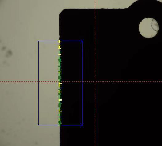

2. Powerful edge-tracing algorithm ensures sampling point accuracy
and automatic pixel correction on sampling stability,
where, one stroke will enable automatic pixel correction, needless
to shift frequently.


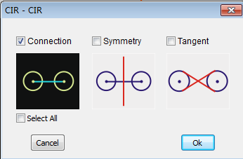
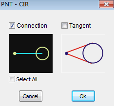
3. Element construction
Element structure technique, offers multiple methods, such as
shifting, rotating, extracting, combining, paralleling,
plumbing, mirroring, symmetry, intersecting, tangentially
structured elements; Element structure will enable user to
tackle some elements hard to measure, and consequently resulting in
increased working efficiency; The compositional
process is to select elements for compositional involvement, select
the result element, clear and simple. Options for
composition methods available in form of illustration.
4. Powerful tagging function
Available in multiple tagging types, for example, tagging of
Distance, Angle, X Distance, Y Distance, Radius, Diameter,
Arc Length, and etc., allows to change position after tagging is
finished, as well as to automatically tag user, that will
remain after program is over.

5. Probe measuring
Powerful functions of software probe measuring enable to character
2D & 3D elements such as height, plane, cylinder,
cone, sphere, ring, etc., and support multiple methods for
establishing 3D coordinates system, with rapid and efficient
programming.
6. Composite measuring of probe and image
Composite measuring by complementing probe with image optical
system achieves multi-purpose measuring of image
and probe.
7. Workpiece array and array macro function
Such function is applied in automatic image measuring instrument.
When a bunch of identical workpieces are placed and
literally equally spaced on one measure fixture, measure one of the
workpieces at first, before measure all the
workpieces on the measure fixture. This will not only save the time
for edge-tracing measuring, but also simplify the
user program.
8. Laser measuring
Laser measuring sees an increasing popularity in imaging device
measuring. Our software is also improved and
optimized responding to the measuring call. We herein introduce as
below:
9. Connection and interfacing with laser
Currently, our measuring device can connect with laser of following
brands: Keyence, Panasonic, Omron, Miyi, Stil,
ERT, Sunny, and etc. Select the laser and COM you wish to connect
with in the Laser List in the Parameter Setting.
(After connection, the measuring method using laser measuring is
indicated as below(L: Reading of the line is the
current laser reading, and corresponding interface of laser
measuring will also pop up in the Graphic Zone)


