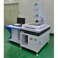
Automatic Non Contact Measuring Equipment For Die Cutting / Screen
Printing
Mechanism and Application Characteristics of Coordinate measuring
machine:
1. Construction of the instrument:
Designed with workbench of a marble panel base and cantilever-type
mechanism, the instrument is characterized by steady accuracy, good
adaptability to working environment, simple, strong, non-deformable
and good-looking body structure, and ergonomically designed
operating mechanism, and meanwhile is equipped with powerful
measuring software and is easy to operate.
2. Movement of Mechanism:
this measuring instrument is provided with tri-axial automatic
control and equipped with Sinpo precision grating system,
high-efficiency motor system, high-standard and high-precision
V-type guide rail as well as professional measuring software for
measurement.
3. Main functional configurations of instrument:
this instrument is used in coupling with dedicated image measuring
software, high-definition color 650TV CCD, high resolution of
0.7–4.5 folds (special high-definition zoom and fixed-focus screen
optical lens), dedicated computer, LCD, keyboard, mouse (optional) and digital measurement.
4. Saving cost:
This instrument can achieve multiple functions on the same set of
equipment, resulting in saved user costs for repeated purchasing of
measurement devices as well as saved labor costs and equipment
occupation space. It can meet the needs of user enterprises for
greater development in the future and the demand for rapid
expansion of product testing to lay sound foundation for users’
quality assurance.
Technical parameters
Paramter and Model | AMQ430 |
Workbench | Platfom size(mm) | 560X460 |
Glass table size(mm) | 450X350 |
Load-bearing weight(kg) | 20 |
Travel | X axis(mm) | 400 |
Y axis(mm) | 300 |
Z axis(mm) | 200 |
Image and measurement system | Display resolution(mm) | 1/0.5(Optional) |
Instrument precision(um) | (3+L/200)um |
Imaging system(CCD) | HD color |
Zoom objective(X) | Zoom objective 0.7~4.5X |
Total video magnification(x) | 30~190X |
Working distance(mm) | 96mm |
Light source | LED programmable partiton light source(Coaxial light source
optional) |
Outline dimension(mm) | 870X710X1680 |
Weight(kg) | 450kg |
Power supply | 220V AC 50Hz |
Configuration List:
Sequence number | Name | Unit | Quantity |
1 | Main body | PCS | 1 |
2 | Instrument table | PCS | 1 |
3 | AUSKY software | PCS | 1 |
4 | video card | PCS | 1 |
5 | Joystick | PCS | 1 |
6 | Dongle | PCS | 1 |
7 | Computer | PCS | 1 |
8 | Liquid crystal display | PCS | 1 |
9 | Aocheng optical calibration block | PCS | 1 |
10 | Precision probe(optional) | PCS | 1 |
11 | Keyboard and mouse | PCS | 1 |
12 | Specification warranty card certificate | PCS | 1 |
Introduction to the software functions:
A. Ample functions of coordinate system
Can establish multiple coordinate systems on the basis of the
actual circumstance, can switch flexibly data under all
coordinate systems, can achieve conveniently switchover between
straight angle coordinate system and polar coordinate
system, can achieve the save and call-out of different coordinate
system, and can display different modes of coordinate system.
B. Convenient program editing and modifying
Enable to modify conveniently light source data, kinetic data,
focusing data, program location, measuring height, and
etc., as well as can replace existing elements with new elements.
C Ample tolerance functions
Multiple calculations of size and geometric tolerance available;
Allowable for calculating 2D and 3D tolerance, e.g,
geometric tolerance as roundness, cylindricity, linearity,
planeness, etc., as well as tolerances as location, parallelism,
verticality, tilt, concentricity, pulsation, etc.

D. Map navigation, scanning and contour tracking software provides
powerful navigation functions
Can scan whole map by assigning a starting point and finishing
point, and can also import the pictures taken by external
sensors for navigation; The scanning function can be used in
reversing function, can designate starting point and
finishing point of the scanning, and special design algorithm;
allow to increase scanning accuracy and practicality
through filtering impurities; allow to track open or closed
graphics to have contour tracking, so as to obtain desired
contour. Can set number of scanning point, on contour, and software
can automatically calculate scanning spacing.
E. Laser measuring
Laser measuring sees an increasing popularity in imaging device
measuring. Our software is also improved and
optimized responding to the measuring call. We herein introduce as
below:
F. Connection and interfacing with laser
Currently, our measuring device can connect with laser of following
brands: Keyence, Panasonic, Omron, Miyi, Stil,
ERT, Sunny, and etc. Select the laser and COM you wish to connect
with in the Laser List in the Parameter Setting.
(After connection, the measuring method using laser measuring is
indicated as below(L: Reading of the line is the
current laser reading, and corresponding interface of laser
measuring will also pop up in the Graphic Zone)
G. Synchronization of laser and image
Before laser measuring, first to synchronize the laser and image,
before following measuring can be performed. Using a
sample, find a cusp on the picture, before shift the crossline
center to such cusp to call out the coordinate value, before
shift the laser spot to such cusp to call out the coordinate value
of such cusp, click to confirm to wrap up the
synchronization, to achieve the image programming laser measuring.
(With this, in subsequent measuring process, whatever laser spot
mining or imaging spot mining, they can be shifted to
the element center already mined)


